You are here: Material Science/Chapter 1/Crystal Structure
Crystalline and Non-Crystalline
Most of our discussion on this page will have to do with metals. The properties of metals are related to their crystal structures. And of course, crystal structure depends on the bonding and types of atoms. So all three are interrelated – how the atoms bond together, which affects the crystal structure, which affects the material properties. Of course, there are many factors that affect material properties, but these are the main ones we will discuss now.
We’ve already sort of discussed the difference between crystalline and non-crystalline materials. A crystalline material has atoms which are orderly arranged, and the arrangement of atoms repeats itself in regular patterns. The atoms are all bonded to their nearest neighbour. It’s a bit of a neat freak when it comes to how it’s atoms are arranged. Carelessness has no place here. All metals are crystalline. Many ceramics are. Some polymers are. Non-crystalline materials don’t exhibit this level of atomic order and structure. Their atoms are all over the place, with complete disregard for rules and regulations. Below is an image comparing the two. This is a 2D image – imagine a cross section of each material.

There is no one single crystal structure unfortunately, because that would make learning it simpler. No, there are a few of different ways to organize the atoms into a crystal structure. Some of the patterns are simple; others complex and intricate. Metals, for the most part, opt for simple crystal structures, which make them easier to learn and understand. We know that atoms are mostly empty space, with electrons whizzing around in different energy states, and the nucleus in the middle. But for the simplicity of explaining crystal structures, we’ll use the atomic hard-sphere model, where atoms are represented by solid spheres. Like marbles. Or bowling balls if you want to think larger. In this model, these spheres touch to indicate that they are bonded to their neighbour. Of course, we know that atoms don’t actually physically touch, but the hard-sphere model is great for visualizing. Here are how atoms are represented in the Bohr model and the hard sphere model, respectively:

We know that the unit cell is the smallest repeating atomic structure in a crystal. Like Lego blocks are the smallest structure of a Lego structure. If you know the unit cell configuration, then you know the entire crystal structure, because the structure is just repeats of these unit cells. Keep in mind that the unit cell isn’t really real, but just a way to chop up the crystal structure into identical pieces for our own understanding. It’s kind of like marking off borders of countries or states – the land doesn’t know there is a border there. We can look at the atoms inside the unit cell in detail and describe their positions, where the atoms are located inside the cell, and so on.

Usually, the unit cell has three sets of parallel faces. Which is just a fancy way of describing a cube. But not necessarily – it could be a parallelepiped. Don’t remember these shapes? I’ll refresh your grade 4 memory:
Metallic crystal structures are nondirectional; a way of saying that the crystal structure is the same in all directions. This is because the bonding type is metallic, which is where electron clouds hold together positive ions like glue. And since that bonding is non-directional, the crystal structure is too. This makes for densely packed atoms. (An interesting fact: when atoms are represented by the hard sphere model in metallics, those atoms are the positive ion cores. The loose valence electrons floating around aren’t shown).
Face-Centered Cubic Structure
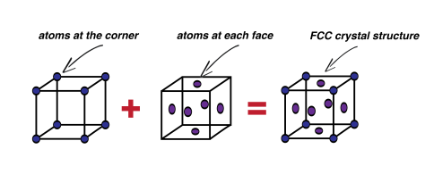
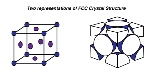
First, I’ll introduce the infamous face-centered cubic, or FCC, crystal structure. Infamous, because I could never remember what FFC stood for. This unit cell is a cube. There are atoms (or positive ion cores; sweet name) at each of the cube corners. And an atom located at each face of the cube, which is where the face term comes from. Here, we’ll just use a stick model to show where the atoms are located in this unit cell:
How many atoms?
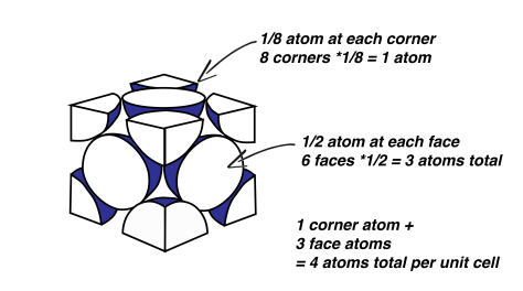
FCC is employed by some very useful metals, such as copper, aluminum, gold and silver. Imagine where we’d be today without FCC crystal structure. Each corner atom of the FCC structure is shared by a total of eight unit cells, which seems impossible but I’ll illustrate this point for you. Basically, imagine 4 blocks, like children’s building blocks, neatly pushed together on the floor to make a square. Pick the centre off the four blocks on the top; that will be the 4 corners of the blocks that are touching each other. Now imagine an atom located at this corner. It will be shared by four unit blocks. Now if we stack another layer of four blocks on top, we’ll get a total of eight. And since these unit cells repeat, every corner of every block shares the corner with seven other blocks. The atom located on the faces of the cube is only shared by two unit cells, since only two faces can touch, which is easy enough to visualize.
So how many atoms are actually in each unit cell? Since each of the corners are shared by eight unit cells, that means that one eighth of each corner atom belongs to a particular unit cell – we’ll call him Bob. Bob is an FCC, which means that he has 8 atoms, one at each corner of his cube. But those aren’t wholly owned by bob! He must share these atoms with his other neighbours. So Bob only owns one eighth of each, which adds up to one whole atom. Bob also has 6 face atoms (6 faces on a cube) which are shared by him and just one other neighbour. Since Bob owns half, he owns another three whole atoms, for a grand total of 4 atoms. Each unit cell in the FCC model has a total of 4 atoms.
Remember, this unit cell stuff is kind of arbitrary. A face atom could easily be a corner atom; there is no difference between the two atoms. It’s just a way of chopping up the crystal structure artificially so that we can describe the position of atoms. I like to think it’s something we’ve done to complicate everything. It certainly did not make sense to me the first time around.
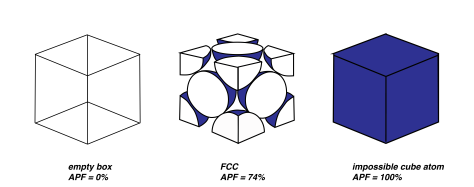
Something that is more interesting is the atomic packing factor, or APF. This is simply the sum of all the volumes of all the atoms in the unit cell, divided by the total space in the unit cell. If the unit cell was just a giant atom, and the atom was a shape of a cube, then the packing factor would be 1: the entire unit cell space is consumed by atoms. If there were no atoms, it would be 0. With atoms being represented by spheres, there are some gaps and air pockets. Think of a bucket of golf balls. There’s still space in the bucket right? You could still pour a substantial amount of sand into the bucket even though it’s full of golf balls.
Atomic Packing Factor of FCC
With our spheres and the FCC crystal structure, the APF is 74%. 74% of the unit cell is occupied by atoms, and the rest is empty space. (But remember this is assuming the atoms are ‘hard spheres’. The true space that the atoms occupy is hugely less, since atoms are mostly empty space). Turns out that 74% is the maximum packing factor you can get with spheres of the same size. If you neatly arranged a bunch of basketballs in a empty swimming pool to have an FCC structure, about 74% of that pool would be occupied by basketballs. The rest of the pool would still be empty space. Here’s something interesting too: if you threw those basketballs in haphazardly, the packing factor would be closer to 64%. Some of them would be arranged nicely, but some would get stuck in weird positions and take up more space. Metals have large APFs due to the nature of the metallic bonding and how the electron clouds hold all of the positive ion cores in tightly.
Body Centered Cubic Structure and Hexagonal Too
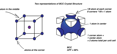
You might be asking, are there other crystal structures other than FCC? Of course. What about body centered cubic? BCC is very similar: instead of an atom located at the face of the cube, there is one in the centre. There are still atoms at each corner. Now, the total number of atoms in the unit cell is 2. Remember, the centre atom and the corner atoms are identical: we could shift the imaginary cubic frame of the unit cell and the centre atom would become a corner. That’s why the unit cell is the smallest repeating unit! BCC has less atoms packed in, and a smaller APF of 68%. So it is a little less densely packed than FCC. You might think it should be lower because it has less atoms, but remember that the overall volume of the unit cell is also smaller, so it all works out.
There’s also the hexagonal close packed crystal structure. This guy isn’t cubic; the unit cell is hexagonal. Think of a stop sign that has a length to it as well. The top and bottom faces contain six atoms at each edge, with a atom in the middle of the face as well. At a plane halfway between two faces is another 3 atoms. Now remember that some of these atoms are shared with other until cells, so each hexagonal close pack unit cell contains a total of 6 atoms. It also has an atomic packing factor of 74%. What crazy metals would prefer this crystal structure, you wonder? Cadmium, magnesium, titanium and zinc are all fans and have signed on to be hexagonal close packers for life.
Calculating Density for FCC, BCC and Hexagonal
What’s slightly interesting about all of this is that we can calculate the theoretical density using all of the knowledge we have gained so far. We are getting somewhere, because knowing the density of materials is pretty important. Density, of course, is just a measure of how much mass a material has, relative to it’s volume. Rocks are dense. Styrofoam is not. How would we calculate the density? First we need the number atoms in each unit cell. We know this for FCC and BCC and Hexagonal because we calculated it above.. Then, we can multiply this number by the atomic weight. Which is easy enough, we just have to look up atomic weight. So now we have the total mass of the atoms in the unit cell. We need the volume, which can be easily calculated by someone other than me. But take my word for it that others have done it. So divide the mass of all the atoms in the unit cell by the volume of the unit cell, for atomic mass per volume. But we don’t want atomic mass, which has units grams per mol. So divide by avogadro’s number to get pure grams. Now, we have grams per volume – a common unit of density. All from know the bonding type, what the elements are, and how they are packed together in the unit cell. Amazing.
Intro to Carbon
A brief respite from talking about metals here: Carbon is an interesting element, and it exists in several familiar states. We talk about it separately, because it doesn’t fit that well into the classifications we’ve already discussed. It’s not a metal. It’s not a ceramic. It does it’s own thing, and is treated as such. Although, graphite can be classified as a ceramic. Graphite, as in what we use for pencil leads.

“Graphite-unit-cell-3D-balls” by Benjah-bmm27 – Own work. Licensed under Public Domain via Commons.
Diamond is a meta stable carbon polymorph. It’s definitely not a commonly used engineering material in the typical sense, although it’s properties make it very useful for some applications which we’ll take a look at quickly below. Below is the unit cell for the diamond crystal structure. The bonds are totally covalent; the carbon atoms all share electrons. Each carbon atom bonds to four other atoms.
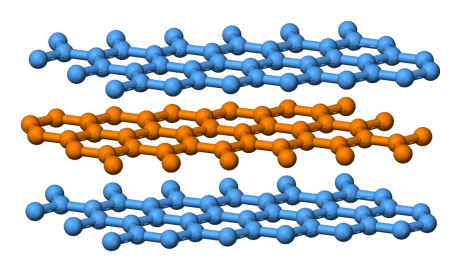
“Graphite-layers-side-3D-balls” by Benjah-bmm27 – Own work. Licensed under Public Domain via Commons.
Graphite is more stable than diamond and has a completely different crystal structure. The way the atoms are bonded together looks like stop signs fitted together like puzzle pieces, side by side. Another word for side to side is coplanar (on the same plane). Another word for stop signs is hexagonal. So graphite has a structure of hexagonally arranged coplanar carbon atoms; with each atom bonded to it’s coplanar neighbour by covalent bonding. But there is also weaker bonding in the vertical direction between the sheets.
Lattice Parameters
We want to talk about the significance of different crystal structures and how the atoms are arranged, but we need a way of describing these crystal structure with more precision so that we’re all on the same page. Unfortunately, this way of describing the systems may have seemed simple to the scientists that came up with it, but it’s not always so easy to understand or visualize. So we’ll go through this part simply and slowly – just enough information so that the following sections will make sense.
So we have these different unit cells, correct? Within these unit cells we have atoms that occupy different positions. How do we describe where these atoms are? One way is similar to describing where a location is on earth: using a coordinate system, like latitude and longitude. But whereas the earth is just a surface, we need to describe all three directions, so an x, y, z coordinate system is ideal. The origin of this coordinate system is conveniently located at the corner of the unit cell. The length of the unit cell edges is represented by three parameters: a, b, and c. Just as if you were asked to describe the dimensions of a box: length, width and height. The angles between the faces of the cell is are denoted alpha, beta, and gamma. Of course, we’ve mostly talked about cubic crystal structures, which is the same shape as a box, and so all three angles are 90 degrees. As well, all the edge lengths are the same: a=b=c. Both the FCC and BCC crystal structures are cubic; they’re nice and simple. So we have a total of 6 parameters – 3 lengths, and 3 angles – which totally describes the shapes of the unit cell. We also have a coordinate system – x, y, z – that we can use to specific any location within the unit cell. That’s a good start for being able to describe the exact shape of the unit cell and where all the atoms are hanging out.

“UnitCell” by Mcpazzo – Own work. Licensed under Public Domain via Commons – https://commons.wikimedia.org/wiki/File:UnitCell.png#/media/File:UnitCell.png
For example, if the cell was 3x3x3, then a, b, and c would all be 3. The angles alpha, beta, and gamma are 90 degrees. If we wanted to describe the middle of the box, then x would be 1.5, y would be 1.5, and z also 1.5. Simple enough.
But the problem is there’s so many more than just cubic! We won’t learn about them, because it gets tedious and, honestly, FCC, BCC and hexagonal are the main ones you’ll learn about. If you pursued materials science more you certainly would learn the rest. I’ll recite a few of the other crystal systems here for you: besides cubic and hexagonal, there is tetragonal, trigonal, orthorhombic, monoclinic, and triclinic! And more, probably.
The Difference Between Crystal System and Crystal Structure
A point should be made about the difference between a crystal system and a crystal structure. The crystal system is the shape of the unit cell as defined by the parameters discussed above. A crystal structure is how atoms and molecules are arranged to make up the material. Which I hope makes sense, because it’s not as clear as the difference between an apple and an elephant. An example of crystal system is a cubic system, and a crystal structure could be FCC or BCC or hexagonal.
Polymorphism
A couple of definitions are in order here. Not all metals have only one crystal structure all the time. Some materials are more interesting than that! For example, Tin has two different crystal structures depending on the temperature. The ability to have more than one crystal structure is termed polymorphism. Poly, for many, and morphism, for the fact that it has the ability to morph into different structures. Another term to describe this in solids is Allotropy. Tin is polymorphic, and it undergoes an allotropic transformation when it changes from one crystal structure to another.
Coordinate Systems – Points and Planes
Points
At this point we’ve discussed that we need a way of describing the geometry of these crystal systems. We’ve done this using lattice parameters. If I wanted to talk about a certain atom within a unit cell, it would nice to be able to say precisely where this atom is located by giving coordinates, without having to draw the unit cell and point with my finger to its location. We’re not only interested in particular points within the cell, but also planes. So we’ll need a system for both. We already talked about how to describe a point with x, y, and z coordinates, but it turns out that material scientists tend to use different letters.
For point coordinates, it’s relatively simple. First, we need to agree on a starting point so that the directions make sense. This is the origin, located at the corner of the unit cell. Now, we know that the sides are labeled a, b, and c. These are really just the x, y, and z directions. Instead of x, y, and z, convention is to use q, r, and s. But they represent the same thing. Whereas a, b, and c are the total lengths of the edges, q, r, and s are fractions of those lengths, which we use to describe the location of any point (we’ll designate this point as ‘P’) within the unit cell.
Let’s do an example. Say our system is cubic and the edge length is 0.5, so a, b, and c = 0.5. Now say that we want to locate the point that has the coordinates 0.25, 0.1, and 0.5. What values of q, r, and s will get us to that point P? 1/2a, 1/5b, 1c.
Crystallographic Planes
Crystallographic planes are a bit more difficult and we’ll only do one example so that you at least understand some of the basic behind them. It’s important to at least understand what planes are and why they matter – be able to describe them and how they are located is not as important right now. Imagine you have a unit cell of BCC crystal structure. Now take a piece of paper and imagine that it is perfectly rigid, so that it remains straight and flat. This is your crystallographic plane. Remember that while a piece of paper has a finite size, a plane extends in all directions forever. It is an infinitely sized piece of paper. You can divide the unit cell using the piece of paper any way you like, by rotating it at the center of the cell. In this way, there are many, many ways to divide the unit cell with this piece of paper.
We’re really only interested in a few different planes, however. We’re mostly interested in planes which contain atoms. Imagine arranging the piece of paper so that it goes through the unit cell diagonally, from the upper edge to the lower one. How many atoms would the piece of paper go through? In other words, how many atoms lie on that crystallographic plane?
This is what we’re interested in. The properties of the material will be partially dependant on the maximum planer atomic density of crystal structures. More on that later! First we need a way of describing how this piece of paper, or crystallographic plane, is oriented.
If you think of the plane in relation to the three axes, x, y, and z (starting at the origin) the plane must either intersect with the axis or never intersect – in which case the plane is parallel to that axis. If it does intersect the axis, then we can describe where exactly this occurs. Typing this is almost impossible, so there are a few examples below to show you what I mean. One rule to note about crystallographic planes: if the plane intersects the original origin, then we have to pick a new origin that isn’t intersected in order to describe the plane. You don’t have to worry about this too much. Basically, if the plane passes through the origin then we have nothing to measure in relation to that origin. If you do a lot of work with crystallographic planes then you’ll see what I mean.
The system is similar to describing points. If the plane passes through the x axis at the far edge of the unit cell, at length a, then the x direction is assigned a 1. If it passes through the x axis halfway along the a edge, then it is assigned 1/2. Simple enough. If it never pass through the x axis, then it is assigned a 0. This means that the plane is parallel to that axis. Illustrations will help immensely here:
Let’s show an illustration of the (110) plane for both FCC and BCC crystal structures. You can imagine taking the unit cell of both of these structures and slicing them diagonally with a knife so that their cross sections are exposed. Below is what you’d see for each:
Something else to note is that negative directions are possible. For instance, the plane could intersect the negative x axis at -1. This is denoted by a hat over the number. All combinations of positive and negative directions for each direction of what is called a family of planes. Each plane is equivalent. For example, the {111} family consists of the following planes:
All this talk about planes and how to identify planes! What is it good for? What we’re interested in is the crystallographic planes that have the highest density. You could slice up a unit cell any way you wanted – but there will only be a few planes along which the majority of the atoms lie. The number of atoms that lie on any particular plane is referred to as planar density. There are also linear directions (1D lines) along which the density of atoms is highest; this is referred to as linear density. It turns out that when we examine the way in which materials deform at the atomic level, the planes with the highest densities are of great importance, as slip occurs along these planes. We’ll learn significantly more about slip later on.
But for now, you’ve probably had enough talk of crystallographic planes and directions, so we’ll end that discussion here. It can be tedious work to figure out planes especially, and I like to believe that the method to describe the planes could somehow be improved on. But I suppose this is what made sense to the material scientists or whoever came up with this system, and it makes sense if you use the system often.
Single Crystal and Polycrystalline Materials
Imagine that a piece of material has a perfect crystal structure. Absolutely flawless. Take a block of iron, for example. Imagine that we start with a single unit cell (type BCC) and we continue to perfectly bond atoms to this single unit cell, until we have many many unit cells – we ‘grow’ the crystal structure. Let’s say that the arrangement of atoms throughout the block of iron is perfect. This is called a single crystal. You may have assumed that this happens frequently, but the truth is that this is very, very rare. Usually there is some interruption or defect in the crystal structure, where the bonds aren’t quite ideal, for various reasons. Single crystals do occur sometimes in nature, and we have the ability to grow them in labs, artificially. But it’s very difficult. It’s very difficult because the environment in which this single crystal ‘grows’ must be very well controlled. It is not an easy task to grow a single crystal.
More commonly, the block of iron would be made up of many smaller crystals, each crystal having a perfect structure. These crystals, or grains (as they’re more commonly known), join together to form the final shape – in our case, the block of iron. This type of material is termed polycrystalline – literally, many crystals. But although there are sections of perfect crystal structures – the grains – the block of iron would not be a single crystal, because overall the material is made up of many of them. How do these polycrystalline materials form? We’ll show it below visually. Initially, as the liquid metal begins to cool and the atoms stop moving so quickly, bonding between the atoms begins. At first, there are small crystalline nuclei, which are just areas where a few atoms having begun bonding. These nuclei occur in many places in the liquid metal. As well, these crystalline nuclei have random crystallographic orientations – there are no constraints for which way the nuclei have to be oriented, so they have random orientations. They can basically do whatever they like.
These crystalline nuclei grow as more liquid atoms cool and bond to them. These are the beginnings of individual crystals or grains, which have perfect crystal structures. But these crystals begin to run into other crystals that have been forming from other nuclei as the solidification process continue – and since these crystals have random orientations, they are unlikely to line up and bond perfectly with one another. What occurs, then, is that at the end of the solidification process, the material is composed of many crystals, and at the edges of these crystals (grains) are grain boundaries.
Anisotropic and Isotropic Materials
We know that eventually we’ll talk about material properties: how strong they are, how good they are at conducting electricity, and so on. You may have guessed that these properties have a lot to do with the crystal structure of the materials. But we know that from our brief discussion about crystallographic planes that the arrangement of atoms isn’t perfectly uniform in all directions; some directions and some planes have higher densities of atoms. Run along a certain direction in the unit cell and you might run into two atoms, go another direction and you might see three atoms within the unit cell. Now, say we want to measure how elastic a unit cell of iron is. Imagine that we have the ability to pull on it, and we see how far it stretches. But which direction do we pull on it? It will matter! Say we pull on it in both the [100] and [111] directions. There will be different values of elasticity if we do this, since the directions have different atomic densities, and the bonds between atoms look slightly different from that angle, and so on. So when we quote the elasticity of aluminum, which number do we use?
If a material displays directionality when it comes to it’s properties, it is anisotropic. That is, when the material properties come out different depending on which direction you test, it is anisotropic. As you may have guessed, then, isotropic means that the material gives you the same properties, no matter what direction you test it in. So what would you guess something like iron to be? It has a BCC crystal structure (check). Anisotropic or isotropic? We know that within the unit cell, different directions give different material properties as mentioned above. Anisotropic, then?
Actually, Iron is isotropic. Although each unit cell has directionality, and therefore each crystal, or grain, does too, iron is a polycrystalline material composed of many, many crystals are random orientations. And all those grains oriented in random ways means that everything more or less averages out. The result is that the material behaves isotropically. It has the same material properties in every direction. Of course, this wouldn’t be true for a single crystal of iron, but that is very rare, so you can safely assume that iron has isotropic properties.
Can you think of a material that has anisotropic properties? How about a piece of wood? If you’ve ever split a piece of wood with an axe, you know intuitively to hit it along the grain – to strike it lengthwise, so that it easily comes apart. Trying to split it by hitting perpendicular to the grain – on the side – will leave you chopping away for many minutes, or hours, or days depending on your strength and wood chopping form. If the wood was isotropic, it wouldn’t matter how you hit it – it would break apart the same from an axe blow in any direction. Wood is a composite material, like bone or carbon fiber, and composite materials are often anisotropic. This makes them a bit of a pain to deal with from a materials science perspective, but they are also extremely useful in many applications. We’ll discuss composites at length later on.
These concepts may seem difficult at first. They may also seem useless. But to truly understand the properties of a material and way it behaves the way it does, we needed to go down to this level of detail. Because everything begins at the atomic level. Not being able to see the atomic level, I’ve found, always impedes the ability to learn it – especially if you are predominately a visual learner. But hopefully we’ve demystified it just slightly, with illustrations and plain-speaking. Don’t get too frustrated by the lack of detail, or concepts you may feel that I’ve skipped over. Remember that this served to give a simple idea of major underlying concepts do that subsequent more detailed (and more mathematically oriented) learning makes more sense. It is also my hope that subsequent sections will come more naturally because we’ve begun with the smallest building block of all – the atom!
You are here: Material Science/Chapter 1/Crystal Structure
<— Bonding/Polymers —>
